UHF Gate ZK-RFID808
ZK_RFID808 is a high performance EPC C1G2(18000-6C) protocol UHF tag gate device. Designed upon fully self-intellectual property, it supports fast tag anti-collision operation with high identification rate. It can be directly connected to host, controller and other relative equipments. It can be widely applied in many RFID application systems such as logistics, open conference attendance system, open access control and industrial production process control.
l Self-intellectual property;
l Support ISO18000-6C(EPC C1G2) protocol tag;
l 902~928MHz frequency band(frequency customization optional);
l FHSS or Fix Frequency transmission;
l RF output power up to 30dbm(adjustable);
l Support motion direction detection with embedded infrared sensor;
l Support Inventory and EAS mode;
l EAS mode supports true EAS and EPC emulated EAS;
l Advanced anti-collision algorithm, high identification rate and optional RSSI;
l Low power dissipation with built-in buzzer and LED indicator;
l Support RS232 and TCPIP interface;
l High reliability design;
COMPONENTS
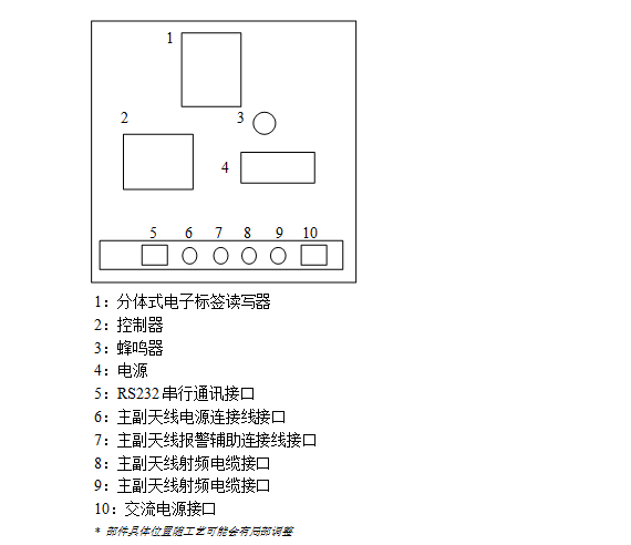
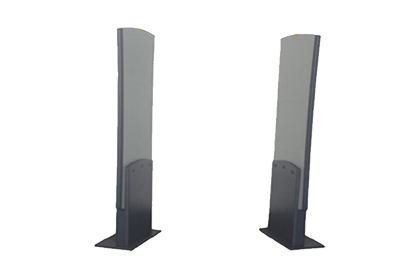
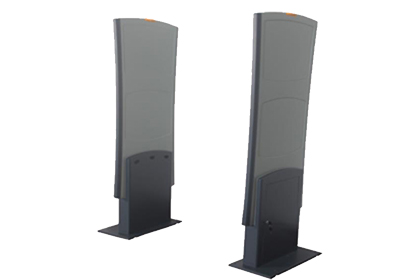
ZK_RFID808 comprises main panel and auxiliary panel. Main panel includes Antenna Array, UHF Fixed Reader, Controller, Infrared Sensor Receiver, Power Supply andInterfacePort.Auxiliary panel includes Antenna Array, Infrared Sensor Transmitter andInterfacePort.
Other accessories include AC power cord, Panel link DC cable, Panel link Alarm cable, Panel link RF cable and RS232 communication cable.
CHARACTERISTICS
|
ITEM |
SYMBOL |
VALUE |
UNIT |
|
Color |
|
Light Grey with yellow/grey edge |
|
|
Height1 |
H |
170 |
cm |
|
Width2 |
W |
60 |
cm |
|
Thickness3 |
T |
15 |
cm |
|
Weight4 |
WT |
40 |
kg |
|
Power Supply |
VAC |
220/50 |
V/Hz |
|
Current. |
IAC |
160 |
mA |
Notes: 1,2,3: Single antenna size
4: Main antenna weight
WIRING INFORMATION
Main panel base box:

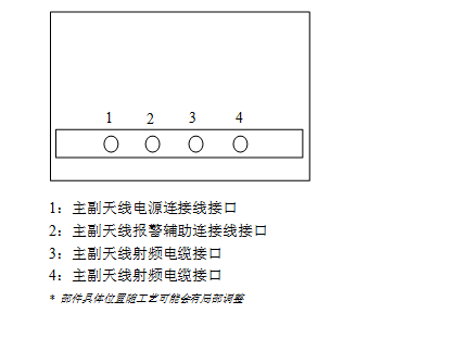
Auxiliary panel base box:

APPLICATION INFORMATION
1. Jumper
setting on controller

|
J1 |
TCP/IP interface socket |
|
J2 |
Relay contactor socket (NC: normal close, NO: normal open, CM: common) |
|
JP1 |
Reserved. For normal operation, JP1-1 & JP1-2 should be shorted and JP1-3 & JP1-4 should be shorted. |
|
JP2 |
JP2-1 & JP2-2 should be shorted to enable RS232 interface. JP2-3 is reserved and should be left open. When choosing RS232 interface, JP3-1 and JP3-2 should all be left open. |
|
JP3 |
JP3-1 & JP3-2 should be shorted to enable TCP/IP interface. When choosing TCPIP interface, JP2-1 and JP2-2 should be left open. |
|
JP4 |
Reserved. JP4-1 & JP4-2 should be left open for normal operation. |
2. Default RS232 serial communication setting: 38400bps, E, 8, 1.
RS232 serial communication socket definition:
|
Pin |
Symbol |
Comment |
|
1 |
NC |
Reserved |
|
2 |
TXD |
RS232 data output |
|
3 |
RXD |
RS232 data input |
|
4 |
NC |
Reserved |
|
5 |
GND |
Ground |
|
6 |
NC |
Reserved |
|
7 |
NC |
Reserved |
|
8 |
NC |
Reserved |
|
9 |
NC |
Reserved |
For detailed information of the communication protocol, please refer to user’s manual.
Remark:
1. Specifications are subject to change, please pay attention to our latest one.

 简体中文
简体中文
 ENGLISH


